Navigation Controls
This section details the navigation controls, placed above the map in the top left corner of the page.

Navigation Controls
Some controls can be hidden through the mission’s configuration file (see Mission Configuration)
Fleet 
The fleet menu shows details and controls about all the vehicles belonging to the current mission.

Fleet Menu
For each vehicle in the mission, there are:
an icon (which depends on the vehicle type: aircraft, UAV, balloon, …) filled with the default vehicle color and the vehicle name ahead.
the date of the last position know for the vehicle. Can possibly be ‘no data’ if there has never been a position for this vehicle.
the air-to-ground connection status: either ONLINE or OFFLINE.
a layer toggler which allows to show/hide the vehicle and its track on the map (by default, all vehicles are shown).
Air-to-ground connection status
As explained above, the connection status between the onboard PLANET server and the ground server is displayed in the fleet menu for each vehicle.
The information is also shown on the map. Each aircraft has a stroke color either red or green which shows this infomration. Green means connected, while red means disconnected.
This information is much more accurate than it was in PLANET legacy version. As a reminder, a vehicle was set OFFLINE if the ground server did not receive a new message for 10 minutes. Now this information shows the state of the TCP connection that is open between the board and the ground servers. If a disconnection occurs, this connection may drop after approximatively 1 minute.
By clicking on a vehicle line, the menu can be expanded to provide more controls.
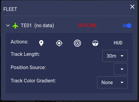
Expanded Fleet Menu
Available actions are:
Vehicle lock on
Vehicle lock on can also be activated by double clicking on an aircraft on the map,
and can be turned off by double clicking the  button or the vehicle again, or by manually moving the map.
The track length dropdown menu allows to select the length (in time) of the displayed track.
The position source dropdown menu allows to select which position frame has to be used to display the track. This is of interest when several position sources are available (GPS, IWG1, …).
The track color gradient allows to select how the track must be colored. By default, this is set to ‘None’. In that case, the track will be uniformly colored with the same color as the aircraft. Two other options are available: either a gradient color by Altitude or by Time (same as in PLANET legacy application). Note that using a color gradient may drop the application performances for some browsers.
Geomarkers 
The geomarker menu provides controls on all geomarker layers.
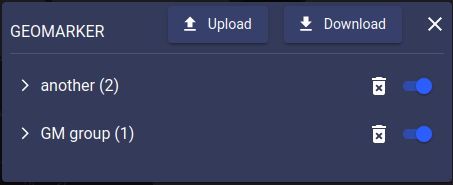
Geomarkers Menu
Each geomarker is now belonging to a group. This information is specified at creation and if not, the geomarker will belong to the “misc” group by default.
All the geomarkers of a common group are displayed on the same map layer.
Each line in the geomarker’s menu allows to control one group of geomarkers (one map layer). Under the group’s name, the number of geomarkers belonging to this group is displayed.
A toggler allows to show/hide the layer.
The button with the trash icon allows to remove the complete group of geomarkers.
Clicking on a geomarker group line will expand the group and show each single geomarker of the group. From here, users can start editing or deleting a single geomarker. For more information on geomarker drawing/edition, see section Geomarker Drawing Controls
Two buttons are available in the header of the geomarker controls section:
Warning
Contrary to PLANET legacy application where geomarkers were displayed during 12 hours, geomarkers are now displayed until they are deleted. Deleting a geomarker won’t fully erase it from PLANET database, but it will be tagged as deleted and not displayed anymore.
Weather 
The weather menu provides controls on all weather layers.
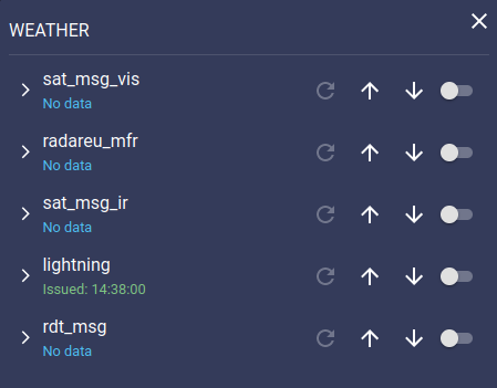
Weather Menu
For each weather layer configured for the mission, there are:
: the product name and the date of the displayed product. If the date is green, the displayed product is the latest occurence received. If red, this is an older one (when using the replayer).
: triggers a request to get the last available product. If already available, product is served from cache (no additionnal download over the datalink).
: allows to reorder the weather layers. The layers are superimposed on the map in the order in which they appear in this control.
a layer toggler which allows to show/hide the weather layer.
Clicking on a weather product line will expand the product and show additional controls:
: opens a popup with information about the product (mainly: source, refresh rate and a color palette if relevant).
: a replayer to show past products. There are two types of weather layer: either raster (image) or vector (kml, geojson, …). Only raster products have the replay control. The replay control only allows to replay products that have been received after loading the application.
On the right side of each weather layer, a toggler allows to show/hide the concerned layer on the map. By default, weather layers are hidden. Showing a weather layer will also trigger a request to the server to get the last available product.
Automatic refresh
Products are automatically refreshed by the system when a new date is available. There should be no need to click on the refresh button.
Cropping products
Products sent to onboard instances may be cropped to save bandwidth. Cropping can either be static (defining a bounding box) or dynamic (a circle around the last known position of the vehicle). The cropping customization is a configuration in PLANET backend, performed upon request by a system admin.
Available products
Several weather layers are available. Depending on the mission loaction, it may include satellite imagery (visible, infrared), radar imagery, lighting strikes, wind & temperature from models.
Custom integration of other weather products is possible upon required.
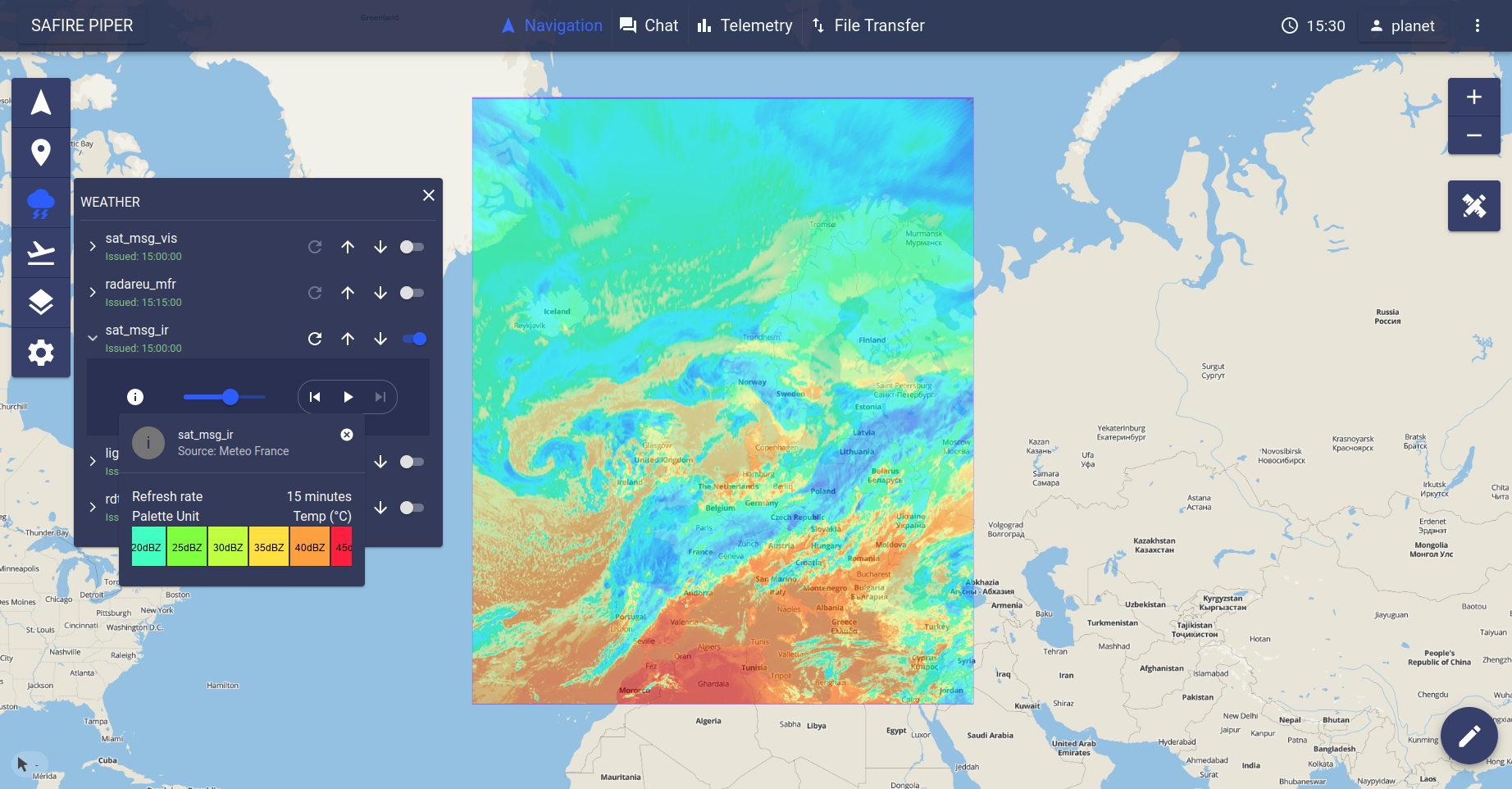
Satellite MSG Infrared Image |
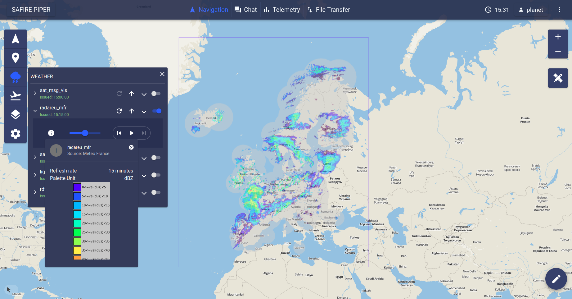
Radar Europe from Meteo France |
Aeronautical Information 
The aero menu provides controls on aeronautical layers.
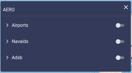
Aero Menu
Airports Layer
The airport layer toggler allows to display airports on the map, as shown on the following figure.
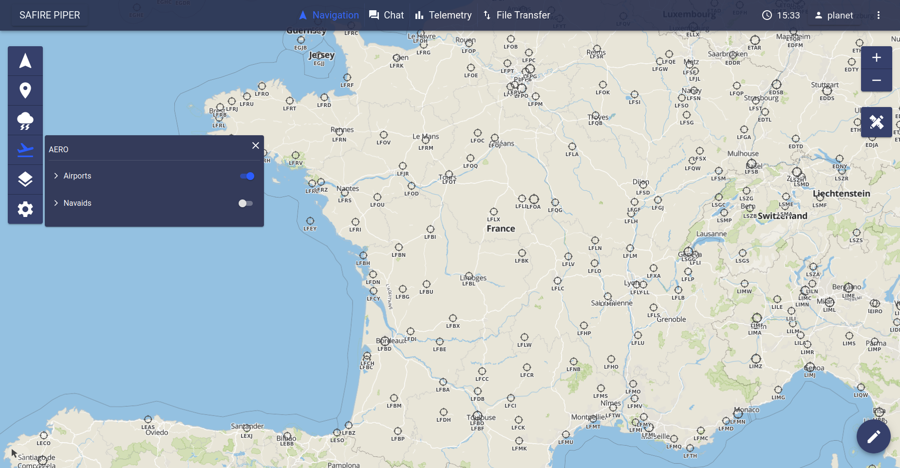
Airports Layer
Clicking on the airports line will expand the section.
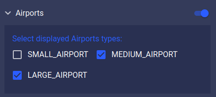
Airports Expanded control
Once expanded, it is possible to select which category of airport to show/hide. Airports are classified in 3 categories: large, medium and small. Even if the layer is toggled, the zoom level needs to be sufficiently high to display the airports. The smaller the airports, the higher the required zoom level needs to be.
Hint
Clicking on an airport opens a popup at the bottom of the navigation page. From the popup, METAR info can be requested by clicking on the refresh button.
If a METAR is available for the concerned airport, the textual METAR will be displayed in the popup after performing the request. As well, the airport icon on the map will be replaced by a graphical representation of the METAR. Graphical METAR display is inspired from https://www.aviationweather.gov/metar .
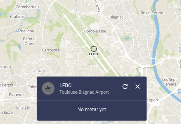
Airport Popup |
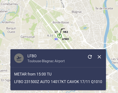
Textual and Graphical METAR |
Double-clicking on an aiport is a shortcut to directly request the metar for the concerned airport.
Navaids Layer
The right-sided toggler allows to display navaids (Navigational Aid) on the map, as shown on the following figure.
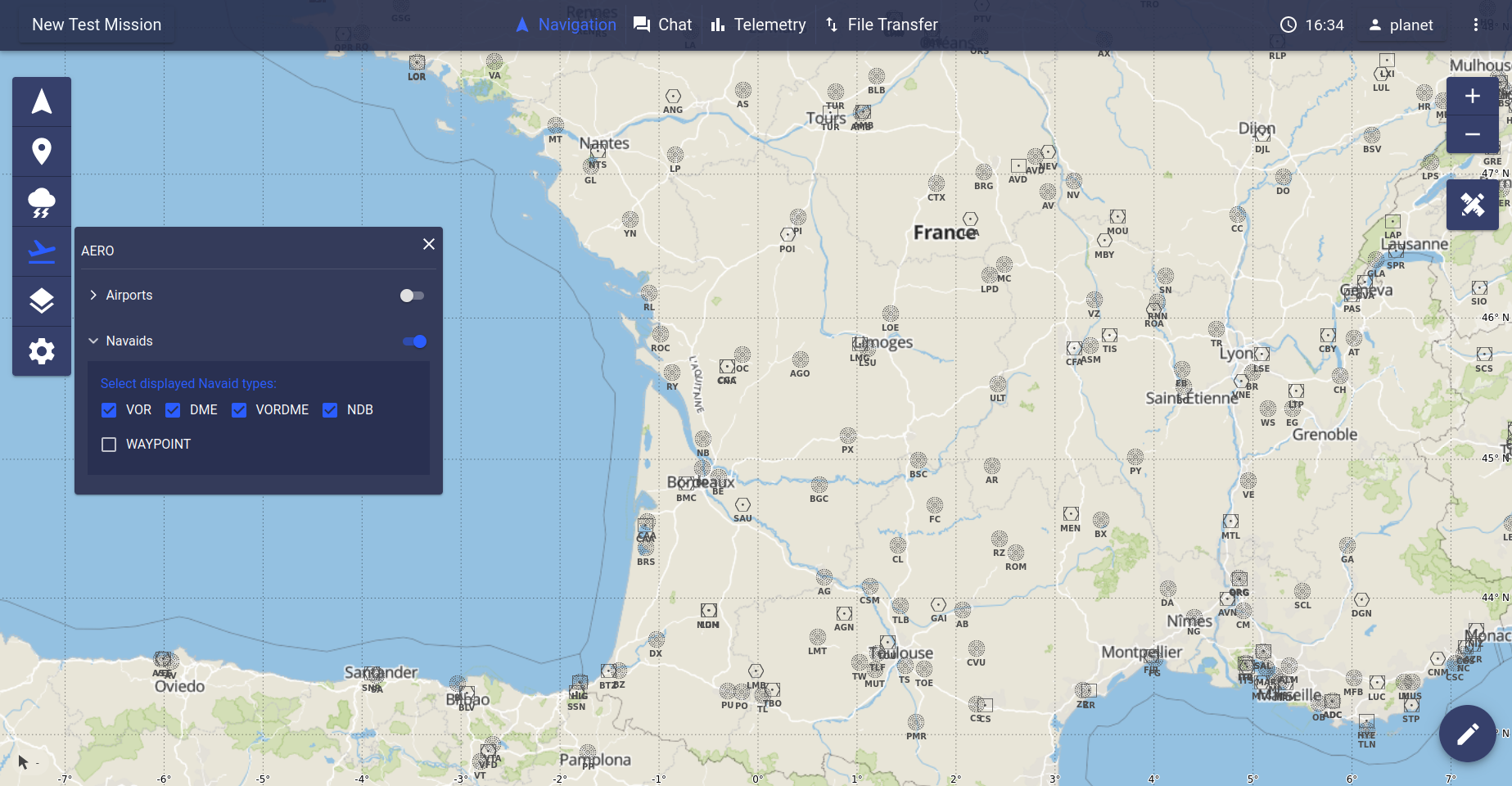
Navaids Layer
As for airports, the zoom level needs to be sufficiently high for the navaids to be displayed.
Navaids are classified in 5 categories which can be activated from the control menu.
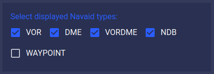
Navaids types selection
Available navaids types are:
ADSB Layer
The ADSB layer toggler allows to display ADSB (Automatic Dependent Surveillance–Broadcast) information, as shown on the following figure.
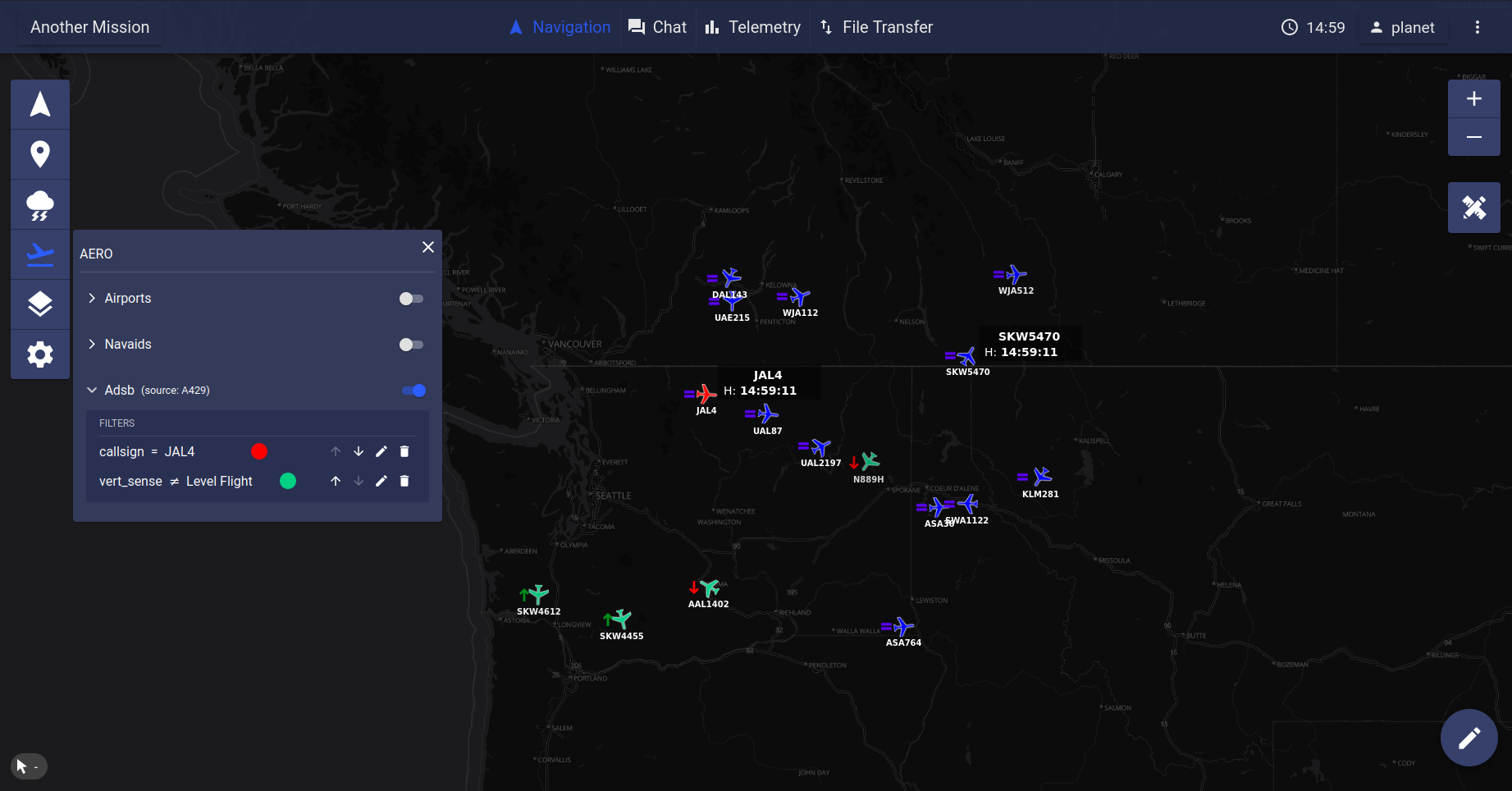
ADSB Layer
Warning
ADSB information may not be available for all missions.
There are two potential sources for ADSB data that can be activated: either an onboard receiver which will get the surrounding traffic or an external ground server which provides such information (FlightRadar24, Opensky, …).
If none of these options is configured, nothing will be displayed when toggling the layer.
For each aircraft of the ADSB layer, a vertical tendency is provided:
either ascending  ,
descending
  or stable
  .
.
Hint
Clicking once on an ADSB aircraft shows/hides its associated HUD (values displayed in the HUD can be configured in the mission config file).
Clicking twice on an ADSB aircraft opens a popup at the bottom of the navigation page, which allows to define filters for coloring aircraft depending on their properties.
Active filters are then shown in the adsb menu, with the possibility to modify their priority order.
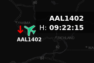
ADSB aircraft with HUD |

ADSB filter popup |
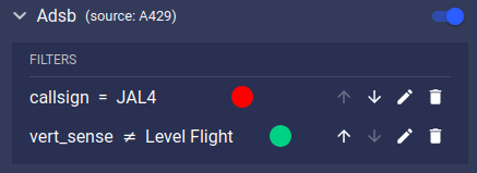
ADSB active filters |
Custom Layers 
This tab allows to add and manage user selected images and vectors over the map.
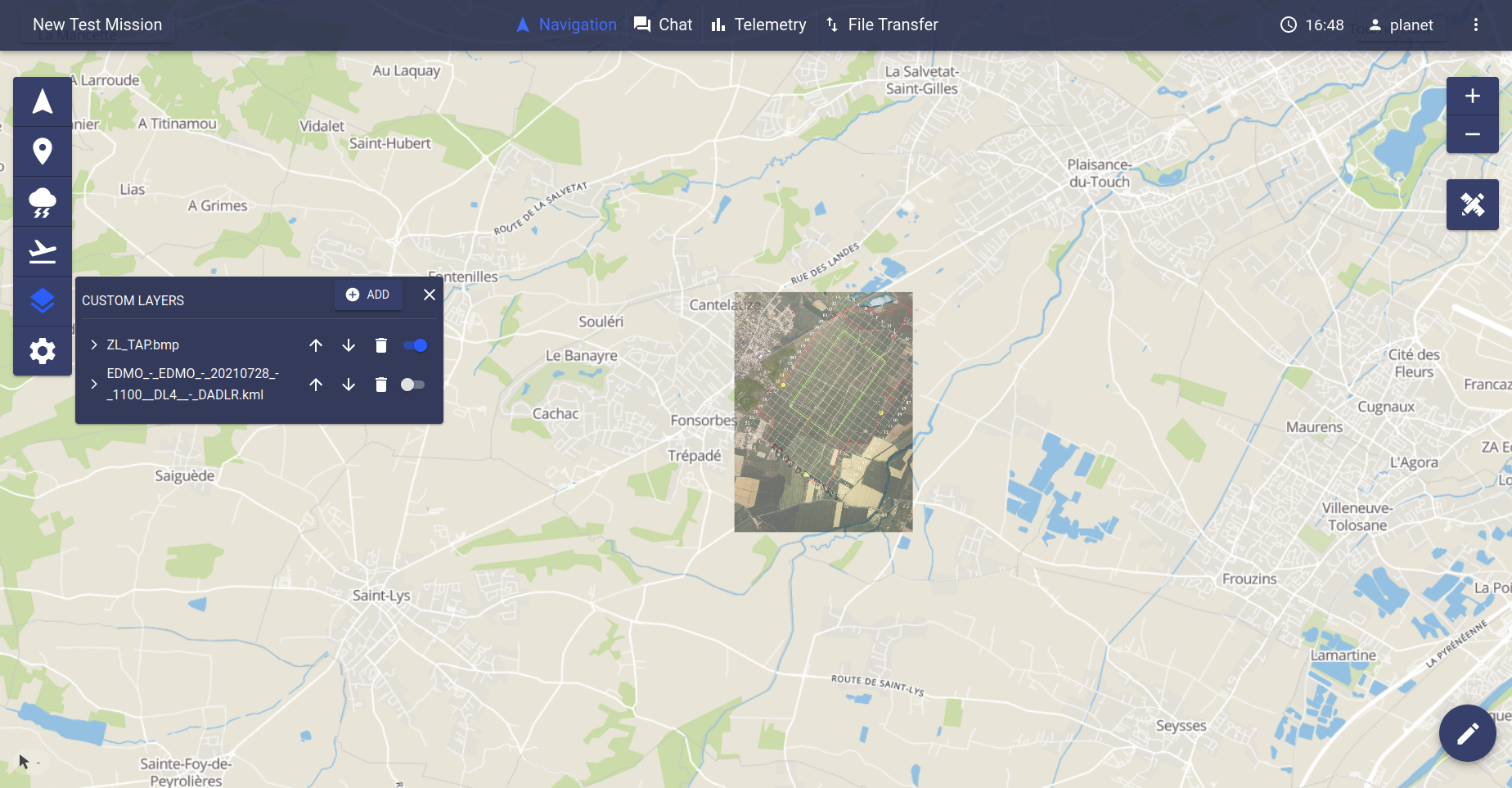
Custom layer
For each custom layer, there are:
Clicking on a custom layer product line will expand the product and show additional controls:
The  button opens a setting window allowing
to add a new custom layer as follows:
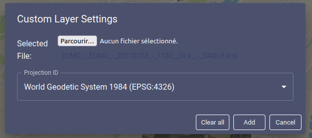
File selection
The user must first select a file to display. Accepted file extensions are ‘.png’, ‘.jpg’, ‘.jpeg’ and ‘.bmp’ for images, ‘.json’ and ‘.geojson’ for vectors (however ‘.json’ files must follow GeoJSON format and syntax).
Once a valid file has been selected, additional fields depending on the file type will appear:
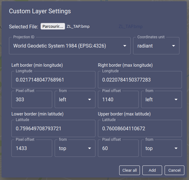
Vector file settings
For vector files, the user must select the appropriate map projections for the coordinates specified within the file.
For image files, the user must fill in the coordinates of the image’s top left corner and bottom right corner in accordance with the projection and unit selected at the top of the setting window.
In case the positions of the corners of the image are not known, coordinates corresponding to points close to the corners on the image may be given along with the distance in pixel from the image corners to said point along the appropriate axis (i.e. horizontal for longitude and vertical for latitude). These distances in pixel must be filled in the corresponding pixel offset fields. The actual coordinates of the corners will be computed from the given coordinates and offset.
If the coordinates of the image corners are known, the pixel offset fields may be left empty.
When creating a new custom layer, the buttons at the bottom of the window will have the following effects:
The ‘Clear all’ button empties each fields and sends the user back to the file selection step.
The ‘Cancel’ button closes the setting window without creating any custom layer.
The ‘Apply’ button checks the validity of the values filled in the fields, then either points out errors or creates a new custom layer with the values filled in and closes the setting window.
When editing a existing custom layer, the buttons at the bottom of the window will have the following effects:
The ‘Reset all’ button at the bottom of the window resets each field to their value before clicking on the
button.
The ‘Cancel’ button at the bottom of the window closes the setting window without applying any modifications.
The ‘Apply’ button at the bottom of the window checks the validity of the values filled in the fields, then either points out the errors or applies all modifications and closes the setting window.
Note
Clicking away from the setting window has the same effect as the ‘Cancel’ button.
Note
In degrees, coordinates values may range from -180° to 180° for longitude and from -90° to 90° for latitude.
In radiant, coordinates values may range from -Pi to Pi for longitude and from -Pi/2 to Pi/2 for latitude.
Pixel offsets can be either positive integers, zero, or left empty.
Note
Adding a new custom layer with a file name already used for another custom layer will fail (i.e. the new custom layer will not be created).
Map Settings 
The map settings menu provides controls on the base layers for the map.
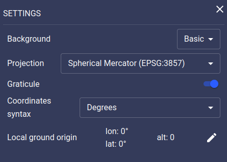
Map Settings Menu
Note
Selected map settings are stored in the localstorage of the browser, which means that any modification will be re-applied at the next connection to the application.
Background
This selector allows to switch between Basic and Dark backgrounds.
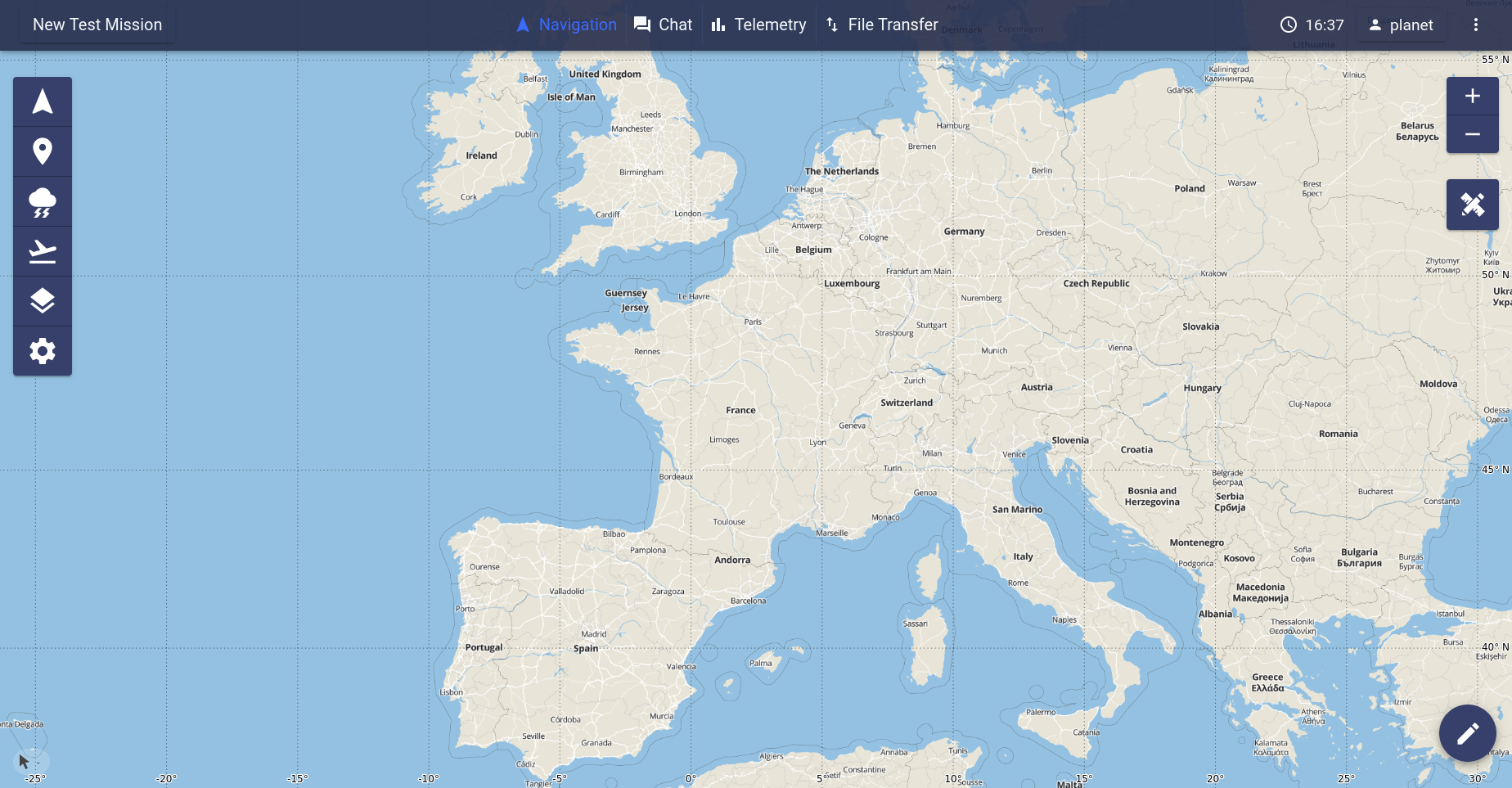
Basic Background |
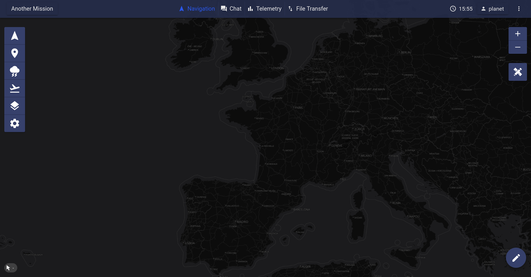
Dark Background |
If enabled in the mission’s configuration file (see Mission Configuration), the Satellite background will also be available.
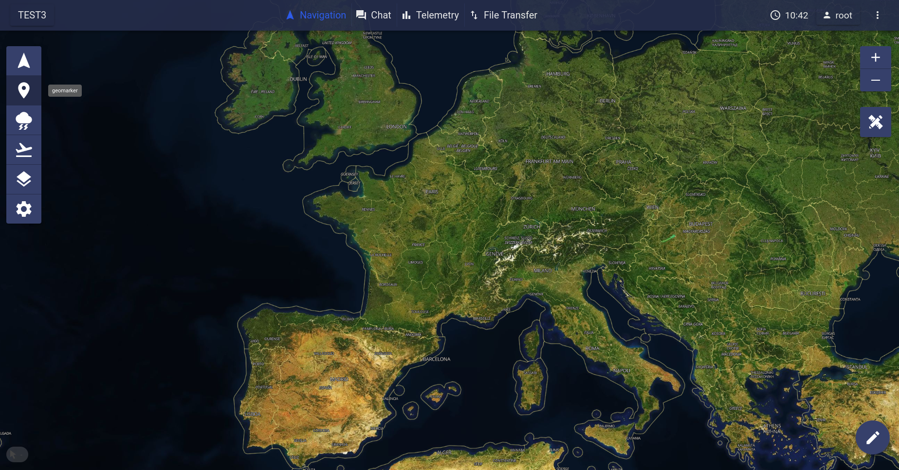
Projection
This selector allows to switch between different projections. For now, only two are available Spherical Mercator (EPSG:3857) and North Pole LAEA Europe (EPSG:3575).
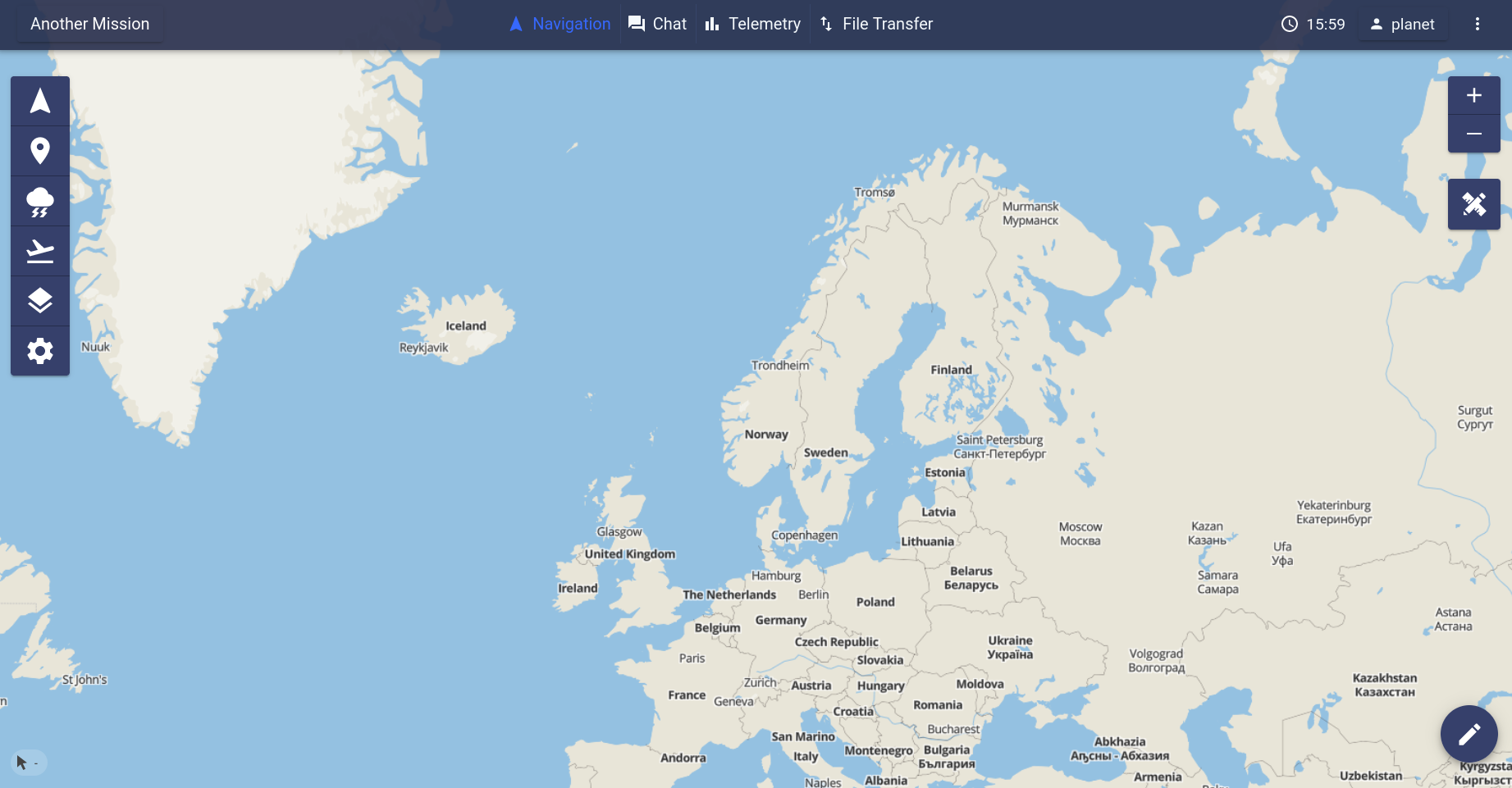
Spherical Mercator (EPSG:3857) Projection |
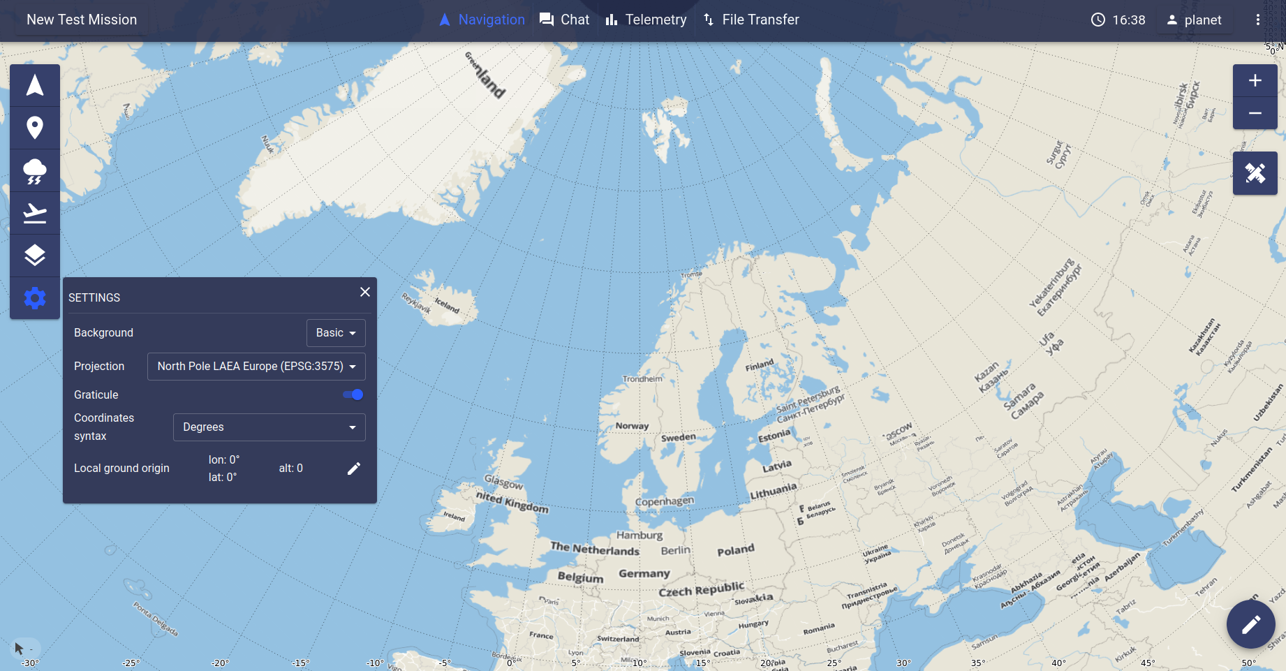
North Pole LAEA Europe (EPSG:3575) Projection |
Note
Any other projection may be configured in the system upon request. To add a new projection, two parameters are required: the proj4 definition and its extent.
Graticules
This toggler allows to enable/disable the graticule layer. This layer renders a grid for the active coordinate system.
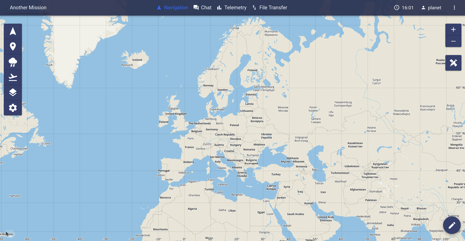
Background with graticules |
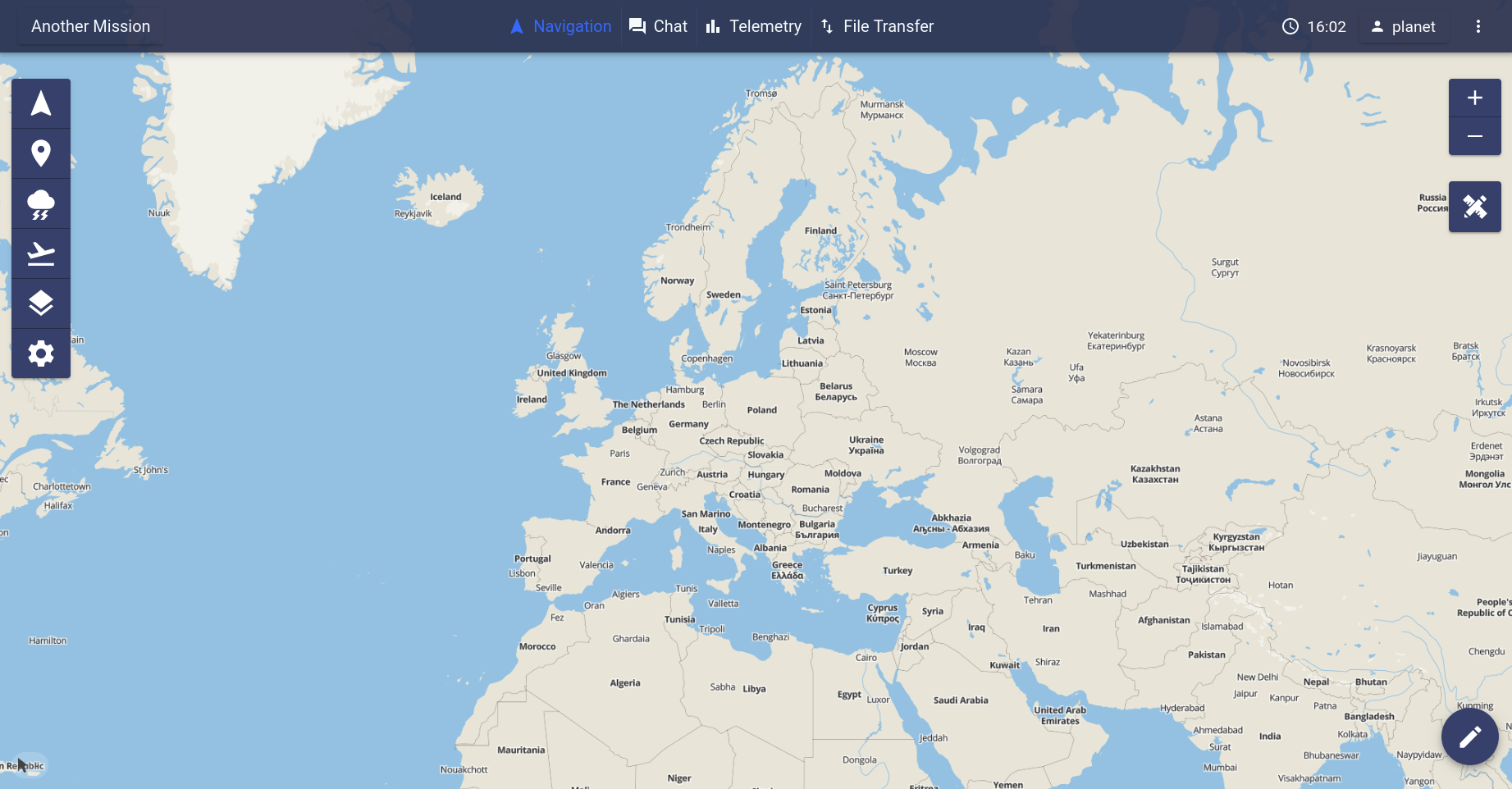
Background without graticules |
Coordinates Syntax
The coordinates syntax dropdown menu allows to choose in which syntax coordinates will be displayed in the application.
Local ground origin
If enabled, the map setting menu will display an additional line allowing to set the coordinates of a point of origin for various computations carried out by the application on aircrafts positions.

Map settings menu with local ground origin settings
The ![]() button opens the following setting window:
button opens the following setting window:
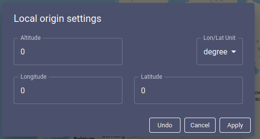
Local ground origin setting window
From this window, coordinates can be set using either polar or geocentric cartesian coordinates.
Geocentric coordinates must be set in meters, earth center being the point of origin, Z being the axis crossing through the north and south poles, X being the axis orthogonal to Z and crossing through Greenwich meridian, and Y being the remaining axis orthogonal to both Z and X.
Polar coordinates must be set in meters for altitude, and in either degrees or radiant for longitude and latitude. The appropriate unit must be selected in the field at the middle right of the window.
The ‘Reset all’ button at the bottom of the window resets each field
to their value before clicking on the ![]() button.
button.
The ‘Cancel’ button at the bottom of the window closes the setting window without applying any modifications.
The ‘Apply’ button at the bottom of the window checks the validity of the values filled in the fields, then either points out the errors or applies all modifications and closes the setting window.
Note
Clicking away from the setting window has the same effect as the ‘Cancel’ button.
Note
Changing the local ground origin will trigger a recomputation of all values computed from aircrafts positions.
Note
When using polar coordinate system, coordinates may range from -180° to 180° (-Pi to Pi in radiant) for longitude and from -90° to 90° (-Pi/2 to Pi/2 in radiant) for latitude.


